Transformation Mappings
Transformation mappings
The Overview section described the basics about mappings. Here, further details are explained.
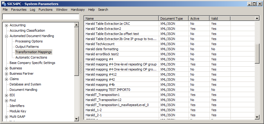
Figure 12 Transformation mapping - selection
From this table you can view, edit, copy, create or delete a transformation mapping. Other options include activating or inactivating a mapping, unlinking the mapping from existing documents, and importing/exporting the mapping. Only valid mappings can be activated.
Import and export are important for copying a mapping from one environment (e.g. test) to another (e.g. production). Multiple mappings can be imported/exported at the same time. The exported mappings are in XML format. The exported mappings are saved to a folder, one file for each mapping, each file named the same as the mapping.
With some limitations, it is possible to export mappings in an XML format that is compatible with a prior version of SICS. To do so, select the ‘Export To…’ context menu option.
When importing a mapping and linking to a referenced Output pattern, the mapping will be updated to fit the Output pattern. For example, assume the referenced Output pattern was recently updated by removing an Output pattern field. If the imported mapping has connections to this field, these connections will be removed.
Note: only XML mappings can be created in system parameters. Tabular mappings must be created directly from an imported tabular document.
The transformation mapping is at the heart of ADH. This is the part that links the input pattern to the output pattern, via a series of links and functional blocks. These links and blocks are graphical representations of the mapping process. A link directly between the input and output will copy the incoming value without modification to the output. Adding a block provides scope for transforming the incoming value in various ways. Blocks can be strung together to create complex mapping processes. A full description of the blocks is given here: Transformation Blocks.
Input Pattern
Whilst the output pattern must be predefined before the mapping is created, the input pattern is created as part of the mapping. For a new transformation mapping, an Input pattern with a default root segment is automatically provided. Alternatively, if creating a mapping directly from a document, the system will automatically create input pattern elements from the source document, which can save a lot of effort when creating the input pattern. The input pattern is always shown on the top left of the validation and transformation tab windows, and no blocks or links may be placed below it.
Even when the pattern is created automatically, it may not contain all the required elements. The Palette section below describes how additional fields and groups can be added to the input pattern.
The input pattern consists of field groups and single fields.
Field Group
A group is used to gather similar elements together, and the group may be set to be repeatable. It’s particularly used where the same data appears again and again in the document - if the document has multiple pages, the page is defined as a group.
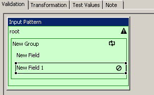
Figure 22 Palette - new field group
The group is indicated by the rectangle around the elements in the group, with the children of the group indented to the right. The topmost element is the group header. It is possible to create further groups within a group.
Clicking on a field group header, you can select ‘properties’ from the menu. Double clicking the item has the same result.
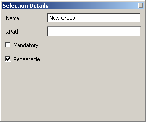
Figure 23 Palette - field group properties
| Property | Description |
|---|---|
Name |
The name given to the group |
xPath |
The instruction to retrieve the contents of the group when mapping. As the input is an xml document, the instruction is an xPath expression. xPath expressions are beyond the scope of this manual. |
Mandatory |
A check box to determine if the group is required or not. A symbol is shown in the Input pattern to show the group is mandatory. A document linked to the mapping that does not contain a mandatory group will create a validation error when an attempt is made to transform the document. |
Repeatable |
A check box to indicate that the group is repeatable. A symbol is shown in the Input pattern to show the group may be repeated. |
A group may be both mandatory and repeatable.
Single Field
Clicking on a (single) field item, you can select ‘properties’ from the menu. Double clicking the item has the same result.
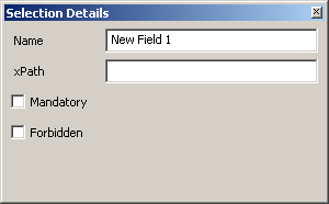
Figure 24 Palette - field item properties
| Property | Description |
|---|---|
Name |
The name given to the field |
xPath |
The instruction to retrieve the contents of the field when mapping. As the input is an xml document, the instruction is an xPath expression. xPath expressions are beyond the scope of this manual. |
Support for table handling within ADH has introduced xPath sub-expressions, which are needed for lookup of row and column headings. An xPath sub-expression is a SICS concept, not an xPath concept, so is described here.
When SICS is about to process an xPath expression, SICS first looks for a substring surrounded by ‘%’. Such a substring is processed as an xPath expression in its own right, and the resulting value replaces the substring and the surrounding ‘%’ characters. This process repeats until all sub-expressions have been processed and replaced. Note: Nested sub-expressions is not be supported.
Example: Looking at the column group within a table, we have this Input Pattern fragment:
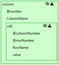
Figure 25 xPath sub-expression
Here, the ColumnName field would have this xPath expression:
../cell[@columnNumber = '%@number%' and @rowNumber = '1']/value
where %@number% is a sub-expression.
| Property | Description |
|---|---|
Mandatory |
A check box to determine if the field is required or not. A symbol is shown in the Input pattern to show the field is mandatory. A document linked to the mapping that does not contain a mandatory field will create a validation error when an attempt is made to transform the document. |
Forbidden |
A check box to indicate that the field is forbidden. A symbol is shown in the Input pattern to show the field is forbidden. A document linked to the mapping that does contain a forbidden field will create a validation error when an attempt is made to transform the document. |
A field may not be both mandatory and forbidden.
Editing a mapping
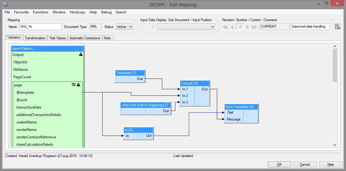
Figure 13 Transformation mapping - edit
The mapping can be opened in view mode or in edit mode. In edit mode, the name can be changed, as can the status and description. Note: changing the name does not create a new mapping - it simply changes the name of the existing mapping. Imported mappings are automatically set to inactive status. After import, the mapping must be activated from the mapping list, or be edited to change the status to active, before it can be used.
Note: Revision support is described in a separate chapter.
The window heading shows these items, left to right:
| Item | Description |
|---|---|
| Mapping name | Common to all revisions. |
| Document Type | XML or Tabular. |
| Status | Common to all revisions. |
| Sub Document dropdown | Enabled when the mapping is opened from a document, and the mapping defines sub documents. |
| Input Position dropdown | Enabled when the mapping is opened from a document. |
| Revision navigator | Enabled in view mode only. |
| Revision status | CURRENT or NOT CURRENT. |
| Description | Revision comment. |
There are five tabs on this window:
| Tab |
|---|
| Validation |
| Transformation |
| Test Values |
| Automatic Corrections |
| Notes |
and one menu button. The menu button can be used to open the Mapping Detail window (see below), or change Test Values Options (see below).
Validation
The validation tab contains the Input pattern and various blocks from the palette (see below). Blocks are added and links made between the input pattern and the blocks to test the validity of the document being processed. For example, if the incoming document includes a fixed template name, an ‘In’ block can be added to test that the document template name is in a list of allowed template names for the mapping (as defined in the ‘In’ block). If the name is in the list, the output from the block is true, but if it is not, the output is false. An error is set if the output from the block is Boolean, is false, and is not connected to another block. Please note: although an unconnected false Boolean will create an error, the use of error blocks provides a better response to the user.
Transformation
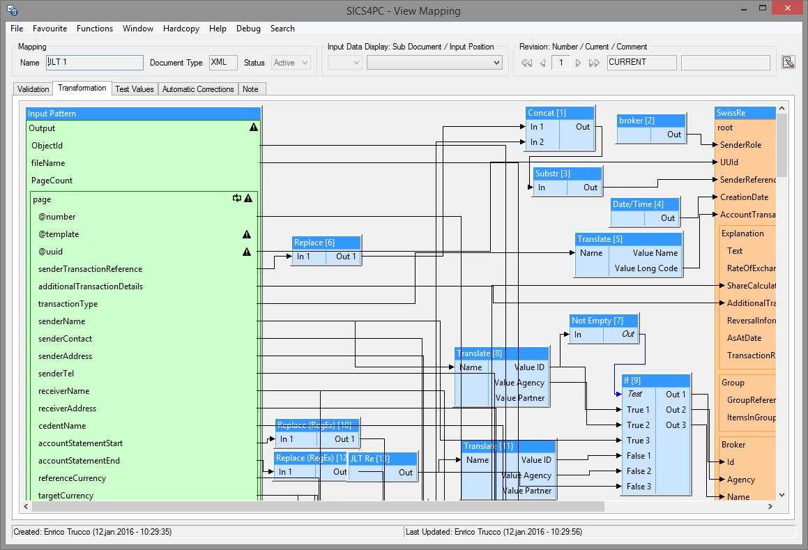
Figure 14 Transformation tab
The transformation tab contains the input pattern defined in validation, and the output pattern. It also contains the graphical links and blocks between the two. The structure of the input pattern can be created and modified using options from the palette. The output pattern (which is defined elsewhere) can be selected from the palette, as can the links and blocks.
Several output patterns may be added to the mapping. Also, a repeatable group within an output pattern may be copied (using the context menu), this allows for setting up different incoming connections to the fields in the group - for example creating multiple IndividualClaimAmtItems in the Tech Account message. The output pattern itself only has one instance, but in the mapping, several instances can be created and populated. The original group and any copies created are still treated as one repeatable group when the output pattern data goes through the final transformation to the output message (using XSL for an XML mapping).
When blocks are added to the validation or transformation, they are un-numbered, but when saved, they become numbered. A new mapping transformation will start with block number 1 (validation blocks also begin at 1, and use their own numbering, independent of the transformation numbering), but blocks added to an existing mapping continue with the sequence from the highest numbered block. If blocks are deleted before the highest numbered block, the number is not reused. For example, if the highest numbered block is 56, and block 42 is deleted, the next block to be added will be numbered 57. There will be no block 42 in the mapping. The block number is used in error correction processing.
Test Values
On the validation and transformation tabs, hovering the select cursor over an item (a field in the input pattern, a link, a block or a field in the output pattern) will show the current value as a ‘tooltip’, but only if there is a document linked to the mapping. If the mapping has been opened directly from the message (see View document below), the current document values will be shown. If the mapping is opened from the system parameter menu, there is no current document, and this tab allows you to choose a document previously loaded in the ADH archive to test with.
Further, you can modify the contents (note: the original document is not changed, only the copy being used for testing is altered) so that different paths through the validation and transformations can be tested. ‘Update’ must be pressed after changing the content before the mapping recognizes the changes made.
If, when hovering the select cursor over an item no value is shown, it implies there is no data - typically this means a block has failed to transform, and, if the mapping were run against a document an error would result. Finding empty values is a helpful technique when debugging a mapping.
Gate (Master) blocks will show red background color when closed, that is, when the currently selected Repeating Group occurrence will be excluded from transformation processing.
Any block which fails (raises a problem) - after applying corrections if selected - will show red background color.
Also, if the mapping is linked to a document, the Input Pattern fields will show input data (test values) according to the selected sub document / input position. Likewise, the Output Pattern fields will show the resulting output values.
Test Values Options
The mapping menu button shows a number of options that affect how test values are calculated and displayed.
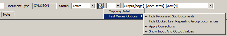
Figure 15 Test Value Options
If the mapping defines sub documents (see elsewhere), then the first drop-down after the menu button will show the sub documents that are present in the current test values. If sub documents are not defined, then this drop-down will be disabled.
The next drop-down shows the Leaf Repeating Group occurrences within the selected (sub) document of the test values.The Leaf Repeating Group occurrences will be listed in sorted order as specified by Sort blocks, if such are present. Otherwise they will be listed in the order given by the test values.
By selecting items from the drop-downs, and/or enabling/disabling menu options, the user can control the tooltip information based on the test values.
Automatic Corrections
This tab lists any automatic corrections that apply when this mapping is used. Although a context menu appears if you select a correction and right-click, the options on the menu are always disabled. To add a correction to a mapping, it must be done from the Automated Document Handling menu in system parameters.
Notes
Here you can add comments about the mapping. This is particularly useful for documenting complex parts of the mapping process.
Mapping detail
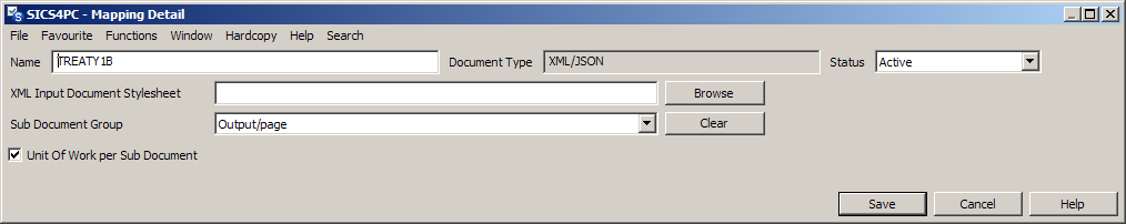
Figure 16 Transformation mapping detail
| Item | Description |
|---|---|
| Name | The name given to the mapping |
| Document type | The document type of the mapping - either XML or Tabular |
| Status | Active or inactive status |
| XML Input Document Stylesheet | The default stylesheet to be used on ‘rendered view’ for a document using this mapping. Stylesheets can be browsed using the browse button |
| Sub Document Group | The sub document group - the dropdown will show all top-level repeatable groups in the input pattern. Any such repeatable group may be chosen as the sub document defining group. IF there are no repeatable groups,the drop down will be empty.A ‘Clear’ button is provided to remove the Sub Document Group setting. |
| Unit of work per Sub document | Indicates if some sub documents will create output messages, when there is error on other. When Unit of Work is false, the whole of the input document must be able to be transformed before any part is transformed. When Unit of Work is true, individual sub-documents can be transformed, whilst other sub-documents remain in error. |
Saving transformation mappings
When trying to save a mapping, the system validates that the mapping is complete. Possible errors include:
- When a block has no input.
- When a block is missing a parameter.
- If the connections form a loop.
- When a mandatory output field is unpopulated.
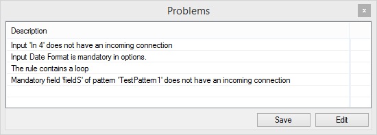
Figure 17 Transformation mapping - errors on save
A list of problems will be shown when an attempt to save is made, and selecting an error from the list will highlight the block or field that is reporting the problem. (Note: this only works if the selected error occurs on the tab being viewed. If the selected error is on the transformation tab, and you are viewing the validation tab, you cannot see the highlighted problem on the other tab).
The problems window includes ‘Save’ and ‘Edit’ buttons. The ‘Edit’ option returns you to edit mode, where further changes can be made. The ‘Save’ option will persist the incomplete mapping, and will set the valid status to ‘No’, and the Status to ‘Inactive’. The mapping cannot be made active whilst ever there are problems with the mapping.
When reopening an invalid mapping for edit, the problems window is re-shown (without save or edit options). Close the problems window to edit the mapping.
When saving a new mapping (or a copy of an existing one), the status will default to ‘inactive’.
Palette
The palette provides the tools to create and maintain the transformation mapping. Within this window are the means to add fields to the input pattern, add blocks to the mapping, select one or more output patterns, and add connections (links) between these.
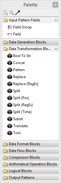
Figure 18 Palette
Select
This is the standard cursor mode, and is used to add fields to the input pattern, to add blocks to the mapping and to select one or more output patterns. It is also used to select blocks already placed in the mapping, and by double clicking (or right click and selecting from the menu), open the block properties. Hovering over an item with the select cursor will show the current value (only if there is a document attached to the mapping - see Test Values above).When adding a new block or output pattern to the mapping, and also when moving an existing block or output pattern, the object cannot be positioned below [and to the left of the right edge of] the input pattern.
Marquee
This cursor mode allows you to select an area of the mapping window. Only items wholly within the select area are included. Using this tool, you can delete multiple blocks, or perhaps more usefully, move them around the window. This can important if you need to create some empty space so that new blocks are not overlaying existing ones.
Connection
The connection cursor is used to make links between input pattern fields, blocks, and output pattern fields. When selected, the cursor symbol changes to one representing an electrical plug. If the cursor is in an area where no connection can be made ‘-‘ is shown by the cursor. Connections must be made from a logical left-to right, from the input side towards the output side. In practice, this means linking from the ‘out’ item in a block to the ‘in’ item in the next block, and physically the first block may be placed anywhere in the middle of the window, including to the right of the next block. The connection remains logically from left-to-right, even though on the graphic, it starts further right than it finishes!
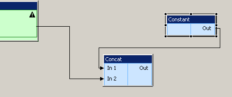
Figure 19 Logical left-to-right
When the connection is completed, the right hand end of the link is changed to an arrowhead.
If a connection, block, input field or output field is selected, the context menu offers a ‘Select Data Path’ option. This highlights the path from input to output.
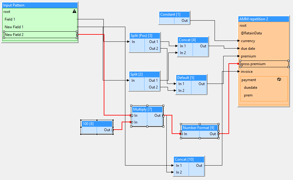
Figure 20 Transformation mapping - select data path
The context menu also offers a ‘Show Data Path Only’ option. This will hide all connections and blocks that are not on the data path(s) of the selected mapping object(s).
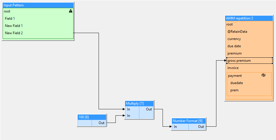
Figure 21 Transformation mapping - show data path only
Finally, the context menu option ‘Show All’ will make all objects visible again.
Connections between non-matching outputs and inputs are not allowed. For example, an ‘Negate’ block expects a numeric input. Connecting from an ‘Empty’ block (which outputs a Boolean), to a ‘Negate’ block is not allowed. Such invalid connections will be reported when an attempt is made to save the mapping.
Input Pattern Fields
This group contains tools to add a field group or single field to the input pattern.
Field Group
After selecting this option from the palette, and placing the cursor over the input pattern, a long bold horizontal line will appear in the pattern at the point the group will be inserted.
Field
When selecting this option from the palette, and placing the cursor over the input pattern, a long bold horizontal line will appear in the pattern at the point the field will be inserted.
Transformation Blocks
Please see Transformation Blocks
Output Patterns
This is the list of active output patterns. Output patterns can only be placed on the transformation tab. It is possible to create multiple outputs from one input document in a single transform - for example, if creating TechAccount and Settlement messages from a single source document (as happens elsewhere for Lloyds accounting messages).
Output patterns have no properties. However, the context menu for the Output pattern allows the copying of repeatable output pattern groups. This is useful say, for TechAccountAmtItems in an ACORD TechAccount message. The output pattern may only include one instance of the TechAccountAmtItem group, but the mapping may need to populate several items in the message. Copying the TechAccountAmtItem group allows many items to be created in the outgoing message.
Automatic Corrections
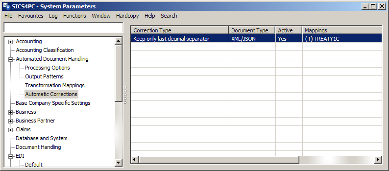
Figure 29 Automatic corrections
For common errors, rules can be provided within SICS to automatically correct the problem. For now, there are two types of automatic correction:
- Keep only last decimal separator
- Ignore ‘No output data’
Other rules can be added on request.
Automatic corrections are only applied automatically if they are assigned to a transformation mapping, and this is done from the Automatic Corrections option in system parameters. Selecting a row in the table and right-clicking opens context menu, where you can choose to:
- View
- Edit
- Create
- Delete
a correction type.
On selecting Create, Edit or View, a new window opens.
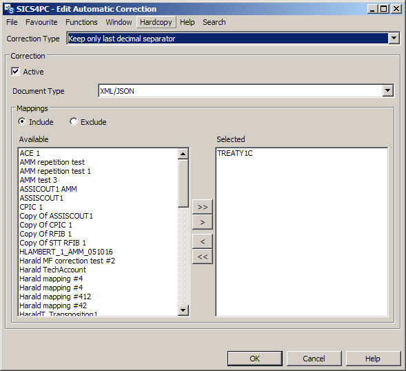
Figure 30 Automatic corrections - edit
In create mode, the window is empty, in view mode the Available column is not shown, but there is an edit button to change to edit mode.
| Item | Description |
|---|---|
| Correction type | A drop-down to select the automatic correction rule. |
| Active | Automatic corrections are active by default, but can be set to inactive if desired. |
| Document type | A drop-down to select the document type. |
| Include | By default, the correction will be applied to all the selected transformation mappings. |
| Exclude | If however, you want the correction to be applied generally, and only not to apply to a limited range of mappings, you can chose ‘Exclude’. The correction will then apply to all the available mappings, and will NOT be applied to the selected mappings. |
| Available | When Include is chosen, the transformation mappings (of the selected Document type) to which the Automatic correction does not apply. |
| Selected | When Include is chosen, the transformation mappings (of the selected Document type) to which the Automatic correction does apply. |
Automatic corrections can also be applied manually during document transformation if they are not assigned to the mapping.
Automatic Correction types
Keep only last decimal separator
This rule will remove all but the last decimal separator from an input field, when this field is input to the following block types:
| Block Type | Only when data type is numeric |
|---|---|
Add |
|
Divide |
|
Equals |
v |
Greater Than |
v |
LessThan |
v |
Multiply |
|
Negate |
|
NumberFormat |
|
Round |
|
Subtract |
|
Truncate |
Each of these blocks includes a parameter that defines the decimal separator.
Example:
If the input document has been misread, and an amount appears in the input pattern as 123.456.78, the blocks above will normally fail, as the input is not considered to be numeric. It is not numeric because there are multiple decimal separators. By applying the auto correct rule, any input to the above blocks that contains more than one decimal separator will have all but the last one removed.
Note:
If this correction is not assigned to the transformation mapping, and one of the above blocks detects a nun-numeric input, the user has the opportunity to apply the correction manually.
Ignore ‘No output data’
This rule will ignore / suppress the ‘No output data’ error which would otherwise be raised when an input sub document does not produce any output.